Distributed Virtual Switch Guide
16 Jul 2011 by Simon Greaves
The vNetwork distributed switch is a vCenter Server managed entity. It is designed to create a consistent switch configuration across every host in the datacentre. It allows port groups and individual port settings and statistics to migrate between ESX(i) hosts in a datacentre, the uses of private VLAN’s (PVLAN) and third party deployment.
vCenter Server stores the state of distributed ports (dvports) in the vCenter Server database. What this means is that the networking statistics, policies and settings migrate with the virtual machine when it is moved from host to host.
The distributed virtual switch is a feature available to enterprise plus license holders with vSphere 4.0 or higher. The vNetwork distributed switch is abbreviated as vDS and is more commonly know as the dvSwitch.
A vSwitch has port groups and ports and the dvSwitch has dvport groups and dvports. This provides a logical grouping which simplifies configuration. Dvport Groups define how a connection is made through the dvswitch to the network. Dvports can exist without a dvport group.
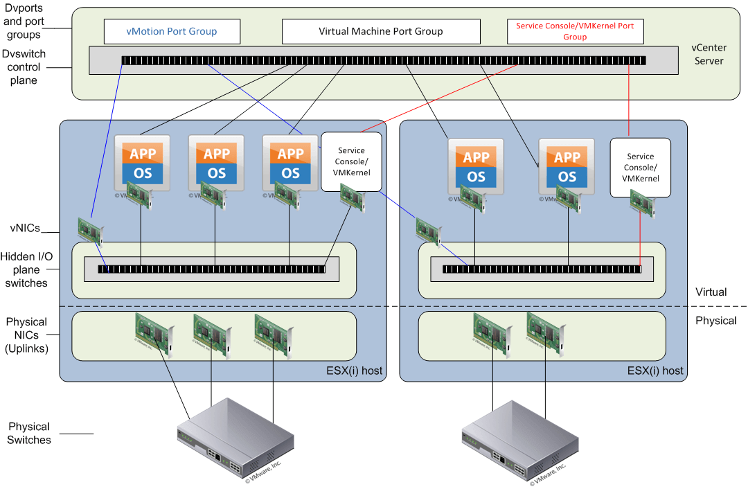
The dvswitch consists of two main components, the control plane and the I/O or data plane.
The control plane
This exists in vCenter Server and is responsible for configuring the dvSwitch, dvport groups, dvports, uplinks, VLAN’s, PVLAN’s, NIC teaming and port migration.
As the control plane exists only in vCenter Server and not on local hosts it is important to remember that a dvswitch is not a big switch spanning multiple hosts but rather a configuration template used to set the settings on each host connected to the dvSwitch. As such two virtual machines connected to two different hosts would not be able to communicate with each other unless the hosts have uplinks that are both connected to the same broadcast domain.
The configuration settings defined on the vCenter Server are on each host are stored in the /etc/vmware/ESX.conf file.
The I/O plane (data plane)
This is the physical input/output switch that exists on each host, it is a hidden switch and is responsible for forwarding the data packets to the relevant uplinks with the forwarding engine and teaming ports on the host with the teaming engine.
Between the virtual NIC (vNIC) in the virtual machine (VM) and the distributed port in the dvSwitch there can also be software filters. These filters are there for things such as vShield Zones and the VMsafe API.
Because of the separation between the control plane and the I/O plane (data plane) the actual data I/O can quite happily run without access to the vCenter server, as such if vCenter goes down the network service will remain uninterrupted. It just means that you cannot add, remove or change any settings on the dvSwitch.

You can use the net-dvs command to display local information about dvSwitches by running:
/usr/sbin/vmware/bin/net-dvs
Uplink groups
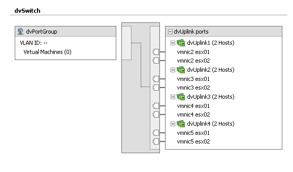
Uplink groups are created to allow for physical hardware abstraction from each host. This means that each host will contribute physical NICs into the uplink group and then vCenter Server will only see and use these groups of uplinks when configuration changes are made to the dvSwitch. This is similar to the way that NIC teaming works. Network policies and rules get applied to the group and each host then translates that information to it’s individual vmnicx.

Dvport groups
Distributed Virtual Port Groups are similar to port groups in that they create port templates that define port policies for similarly configured ports for attachment to VMs; VMkernel ports and Service Console ports.
Port Groups and Distributed Virtual Port Groups define:
VLAN membership
Port security policies (promiscuous mode, MAC address changes, Forged Transmits)
Traffic shaping policies (egress from VM)
NIC teaming policies (load balancing, failover detection and failback)
In addition to these features and functions, a Distributed Virtual Port Group also defines:
Ingress traffic shaping policies (enabling bi-directional traffic shaping)
Port Blocking policy
Port bindings
The Port bindings on a dvSwitch determine when and how the VM NIC is assigned a port in a port group.
There are three different port binding types
Static - dvport is assigned permanently to a vNIC when added to port group. (Default)
Dynamic - dvport is assigned only when a VM is first powered on after joining the port group. This allows for overcommitment of dvports.
Ephemeral - no binding. This is similar to the a standard switch. Port is assigned to every VM regardless of state.
Private vlans
Private vlans are vlans that are created within other vlans. These are especially useful when you have devices that should only communicate outside of the vlan they are in and not with each other.
They can also be used when you have devices on a shared wireless network where you don’t want various wireless devices to be able to communicate with each other or should you run out of physical ports on a switch and you want to create additional separate vlans without having to purchase additional network cards and switches.
Private vlans operate a three different modes
Promiscuous - devices can communicate with all interfaces on the vlan and the ones the uplink is a member of.
Isolated - can only communicate with the promiscuous port they are connected to, so devices in the private vlan cannot communicate with each other.
Community - devices can communicate with each other and the promiscuous port as well.
There can only be one promiscuous pvlan, this is created automatically when you setup a private pvlan.
In order to create a pvlan you need to follow a few simple steps
Step 1. Create the relevant vlans and private vlans on the physical switch and ensure the uplinks from the dvSwitch are members of both vlans in trunk mode.
Step 2. Modify the dvSwitch so that the relevant vlans and pvlans are set
Step 3. Create a dvport group that uses the pvlans. When doing this choose the relevant vlan type as private vlan to then be given the option of selecting the pvlan id created earlier in step 2.
Eric Sloofs video on configuring private vlans with Cisco switches
CDP
CDP or the Cisco discovery protocol works at layer 2 or the OSI model and contains information about neighbouring devices on the network such as routers/switches models, IOS version and port quantities.
Cisco routers and switches can exchange CDP data with vSphere standard and distributed switches. CDP is disabled by default on vSwitches and enabled by default on dvSwitches.
The information it collects and is updated every one minute.
CDP on a vdSwitch can be set in one of four ways
Down - no send or receive
Listen - receive
Advertise - send
Both - listen and advertise
To enable CDP on a switch
esxcfg-vswitch -B vswitch0
View CDP on a vSwitch with
esxcfg-vswitch -b vswitch0
To enable on a dvSwitch, go to advanced settings on the dvSwitch in the networking section of the vCenter Server and tick the box labelled enable CDP.
With the advent of vSphere 4.1 new features were introduced including load-based teaming and network I/O control.
Load-based teaming
This was introduced to add a true network balance on the network adapters in a team. Up until 4.1, teaming in a virtual environment really meant splitting the load across multiple NIC’s, but fundamentally it was not possible to say put two 1GB NIC’s together and expect the load to be split evenly out over the NIC’s, so you could potentially have all traffic travelling over NIC 1 and nothing over NIC 2. NIC 2 would still step in to take out the load if NIC 1 went down, (if configured so) but there would be no guaranteed spilt over the two.
This is what is now available with load-based teaming.
Network I/O control
Network I/O control is used to divvy up the bandwidth I/O on a network adapter, such as a 10GBe NIC based on the priority of the traffic using network shares. As an example you can set vMotion traffic to have larger shares so that it has a fair priority of network time.
This is only available with the dvSwitch.
Creating a distributed switch
-
In vCenter, click
Home > Inventory > Networking.
Note: If you are in other locations, theNew vDSoption is disabled - Right click the Datacenter and select
New vNetwork Distributed Switchand specify the:- Name of the Distributed Switch
- Number of Uplink Ports. Uplinks can be renamed/added afterwards.
- Click
Next. - In the Create vNetwork Distributed Switch GUI, under Add hosts and physical adapters:
- Click Add now or Add later
- Choose the ESX(i) hosts
- Select physical adapter to select adapter per ESX(i)
Note: Click on view details, to see general adapter information and CDP Device and port ID
- Click
Nextand finish.
Note: This automatically creates the default dvPort group, which can be deselected. At this point the newly created dvSwitch is displayed under the DataCentre on the left panel.
Modifying vNetwork Distributed Virtual Switch
- Go to
Host > Configuration > Networking. - Right-click on the desired dvSwitch and click
Edit Settings. - Click
Generaland specify the following:- dvSwitch name (VMware recommends not changing this after full deployment)
- Number of dvUplink ports
- Important administrator notes
- Click
Advancedand specify the following: Max value for Maximum Transmission Unit (MTU) Useful for enabling Jumbo Frames. Supported value is up to 9000. - Cisco Discovery Protocol (CDP) Operation.
Select from the drop down menu the following options:
Listen
Advertise
Both
Hany Michaels over at hypervizor.com has an excellent Visio diagram detailing the functional workings of the dvSwitch. This is quite possibly the best dvSwitch Visio diagram around.
Tagged with: vSphere
Comments are closed for this post.